CFRP has well known associated risks
Carbon fibre reinforced polymer (CFRP) components are increasingly common in the Aerospace and Automotive industries due to their excellent mechanical properties, most notably their high strength to weight ratio. CFRP components are manufactured by laying several uncured resin/fibre plies on top of each other. Once lay-up is complete the material is cured, fusing the plies and giving the material its final properties. Prior to final assembly, it is often necessary to drill fastener holes in CFRP components which can result in a separation of the plies, known as delamination. This delamination can create weakness and result in premature part failure and is a major cause of costly part rejection in manufacture. This report, from the University of Sheffield Advanced Manufacturing Research Centre (AMRC) was undertaken to help industry develop economic methods of controlling drilling-induced delamination.
Our delamination approach offers a better solution
Delamination is quantified in both industry and academia using the ‘delamination factor’. This dimensionless metric is defined as the ratio of the maximum delaminated diameter and the hole diameter. The maximum delaminated diameter is defined as the diameter of the circle which encapsulates all the delamination with its centre coincident with the hole centre, this is a 2D assessment whereas the delamination is 3D. Using a Bruker Alicona μCMM allows the determination of depth and form factors that will indicate if the damage is limited to just the surface ply or if the deeper structural plies are also affected. The measurement task was to capture both a high quality 2D image and a Focus Variation 3D scan of the surface around a drilled hole. The 2D image allowed the delamination factor to be calculated whilst the Focus Variation 3D scan enabled the maximum depth of the delamination to be investigated. The specimen used is a metallic and carbon fibre reinforced polymer (CFRP) stack, typical of assembly structures used throughout the aerospace industry. For this application, both a 2D image and a 3D Focus Variation scan. The 2D image was an Image Field, with the number of images being 9 rows x 9 columns. Using a suitable lateral and vertical resolution the scans were made in both 2D and 3D.
Assessment of this data showed a maximum delamination depth of 131 µm. The approximate cured ply thickness of this material was 250 µm. This shows that the surface delamination is limited to the surface ply only and does not propagate into the structural plies. In addition to the delamination, a checkerboard pattern can clearly be seen in the 3D data. This shows the weave of the CFRP surface ply, and indicates that at the tow interlace, the surface can be up to 120 µm beneath the nominal surface.

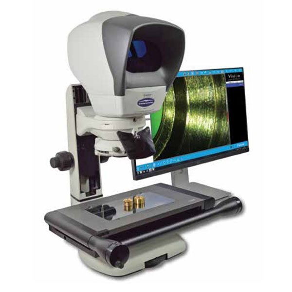
Bruker Alicona μCMM system
Delamination due to the drilling of composite material is a widespread problem within the aerospace industry. The high-quality output of the Bruker Alicona μCMM system, coupled with its ability to rapidly scan multiple holes, allows for the opportunity to develop a reliable automated method of hole delamination inspection.